

The structure of quenching machine tool for Medium frequency quenching heat treatment equipment.It’s kind of Induction heating machine The quenching machine for medium frequency heat treatment and tempering equipment is composed of bed, V bracket, movable rod, reliable sliding table, quenching transformer inductor group, capacitor and quenching slot. The mechanical action is controlled by hydraulic pressure, the V-shaped bracket holds the workpiece up and down in place, and then coordinates the action by the moving rod; the two reliable clamping camshafts on the sliding table move horizontally to enter or send the camshaft into or out of the sensor; the left spindle box of the machine tool is driven by the hydraulic motor to rotate the camshaft. The rotating speed can be stepless speed regulation in a certain range. There is a copper plate grounding ring on the left side of the inductor. If the camshaft is not clamped reliably, the ground ring will be touched first when moving horizontally, generating a signal and stopping the action.
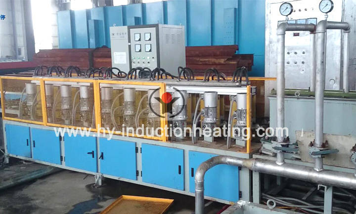
Quenching transformer is a variable turn ratio intermediate frequency transformer, the primary stage is 10 ~ 22 turns, divided into 13 grades, the secondary is 6 turns. The sensors are in series in multiple circles, and nine sensors are located on a center line, eight of which are heated cams. The sensor is double-turn, the gap between the cam tip and the inner diameter of the effective ring is 4 ~ 5 mm, and the sensor base has elliptical holes, so that the sensor can be adjusted relative to the axial position of the cam. The camshaft sensor adopts series, which avoids the disadvantages of short intermediate conductive path and long conductive path at two ends when multiple sensors are connected in parallel. When the series inductor method is used, if the temperature of the intermediate cam is on the high side, it can also be adjusted by increasing the gap. Capacitor bank configuration, using three bottles of 300kvar electric thermoelectric container.
Quenching tank and conveyor chain. The capacity of quenching tank is 1.5m3, the polymer quenching solution Ucon A or 251is selected, its mass fraction is 10%, and the service temperature is 3 ≤ 50C. There is a 6kW tubular electric heater in the quenching tank to adjust the temperature of the quenching solution. There are heat exchanger and water pump next to the quenching tank. The pump sends the quenching liquid with the rising temperature to the heat exchanger, and carries on the heat transfer to the heat exchanger to cool down with the industrial water in the heat exchanger. The control of temperature and flow rate of this system is the same as that of general quenching liquid cooling system, and it is no longer detailed. A sloping conveyor chain is installed in the quenching tank to lift the hardened camshaft from bottom to top to the next process.

Overseas manager: Tom Wang
Email:tom@foreverfurnace.com
Phone: 0086-13303078975(whatsapp, wechat,line)
Specialist of bar heat treatment furnace in China; Glad to be your business partner in induction heating field.
Post time: 06-17-2019